Troubleshooting
At the end of the Settings page, you can see the Troubleshooting section. Use this information to confirm that the video and audio on the TD52 is streaming correctly.
Wire a TD52 Video Intercom
Wire a TD52 Video Intercom
Learn how to wire a Verkada TD52 Video Intercom
Updated over a week ago
The Verkada TD52 Video Intercom provides a Power over Ethernet (POE) port to enable communication with your Verkada Command dashboard and 3 input/output (I/O) ports.
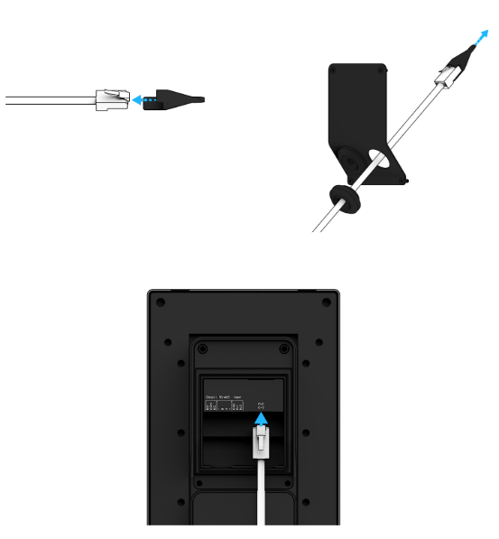
Wire the TD52 into your network
Required. The TD52 requires a (PoE/PoE+)-enabled switch port.
Power: 11.5W (IEEE 802.3af PoE)
Extended Temperature Range: 25.5W (IEEE 802.3at PoE)
The back of the TD52 has an I/O cover is secured by 4 screws that hold the I/O cover in place.
The intercom should power on and the status LEDs display on the face of the Intercom. Read about what each LED status indicates.
Wire the I/O port
The TD52 provides space in the I/O port for 2 inputs and 1 output.
| Input device options | Output device options |
|
• Call triggers
• Door Position Indicator (DPI)
• Request to Exit (REX)
|
• Door unlocks
• Chime
• Call in progress
|
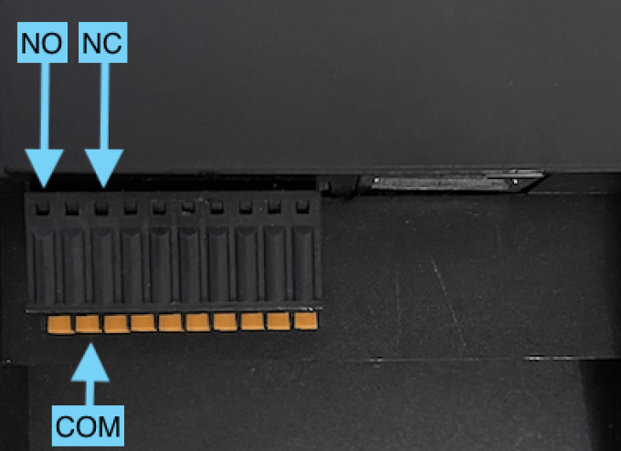
Example: I/O ports when the cover is removed
Each I/O port corresponds to the following pins from left to right:
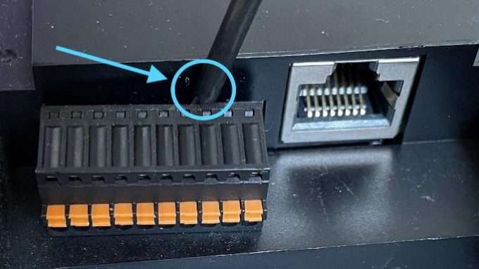
To simplify the I/O port wiring, remove the I/O terminal. You can use a Torx security screwdriver provided in the box or any tool that allows you to lever the terminal away from the device.
Wire an input device
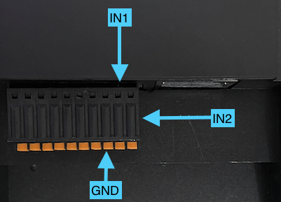
Looking at the I/O terminal, the 3 ports closest to the right are for inputs:
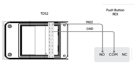
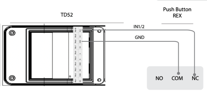
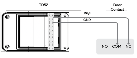
Note the number input; this corresponds to an input number in your Intercom settings. For example, a door position indicator (DPI) wired into IN1/Pin 9 and a Request to Exit (REX) wired into IN2/Pin 10.
Example wiring scenarios
REX / Call Trigger
Door Contact / DPI
Required. When wiring an Intercom as an access controller, you must wire the REX into Input 2 (IN2) and DPI into Input 1 (IN1).
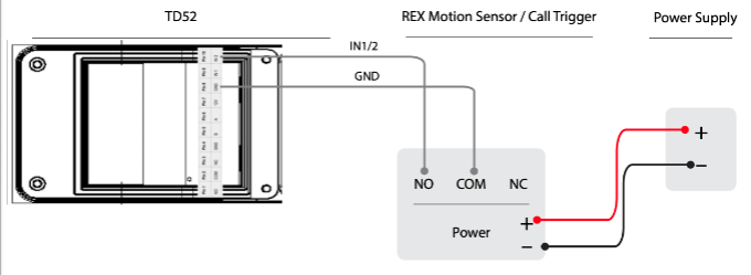
Power your input device using an external power supply
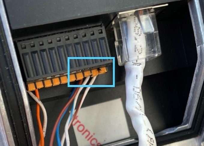
To wire using an external power supply, take the positive (+) and negative (–) wires from the input device and then wire it into the power source.
Example: How to wire a powered REX/call trigger into an external power supply
Wire an output device
Looking at the I/O board, the 3 ports closest to the left:
Note: The TD52 uses a dry relay, which means that it cannot power an output device. All output devices that require power need to use an external power controller or power supply.
Wire a reader
Learn how to wire a reader to an Intercom and use it as a 1-door access controller.
Example wiring scenarios
Door unlock
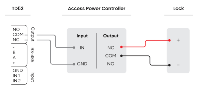
The door unlock allows for the output relay to trigger when an unlock is sent from the receiver. In both wiring scenarios, the lock is attached to an access power controller.
Using a fail secure lock
Using a fail safe lock
TD52 Status LEDs
TD52 Status LEDs
Learn more about the LED status for a Verkada TD52 Video Intercom
Updated over a week ago
The Verkada TD52 Video Intercom uses 2 sets of LED status lights:
Status LEDs
The LED status light consists of the following states:
Example: Fully online and healthy Intercom
Setup progression for status LEDs
When you first turn on the Intercom, a white LED appears. The LEDs progresses as the setup progresses (up to 5 additional LEDs light up). These status LEDs are essentially a progress bar to indicate how far along the Intercom is in first coming online.
The LEDs indicate the following states:
Note: The status bar does not persist after the Intercom is fully configured. The status bar only appears again, after it is decommissioned, and then added back to Command.
Configure the TD52 as a 1-Door AC
Configure the TD52 as a 1-Door AC
Learn how to configure the Verkada TD52 Video Intercom as a 1-door access controller
Updated over a week ago
Before you begin
Set up your hardware before you begin the Verkada Command setup.
Verkada reader
The Verkada TD52 Video Intercom is rated to power Verkada readers at 12V and 250mA via the (+) and (–) connection.
Recommendation. We recommend to connect the drain wire to earth ground at the reader side.
Note: Avoid using 12V power to power other peripheral devices, as it has latch-off current limiting.
Inputs
The TD52 has 2 general-purpose dry inputs. The default input state (Normally Closed [NC] or Normally Open [NO]) for each can be configured in Verkada Command.
Connections
For each input, you should connect 1 wire to the IN pin, and the other to the GND pin. You can connect any device with a dry relay output to these ports, such as door position indicator (DPI), request to exit (REX) sensor, intercom, or access control output. All associated events are logged in Command. Learn more about how to wire the input device.
Output
The TD52 has 1 dry form C relay output that you can configure as an access controller (AC) by connecting an access power controller to the output terminal, as detailed below.
Connections
You can also use the output relay as a general-purpose output.
Learn more about how to wire an output device.
