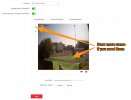
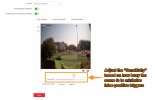
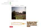
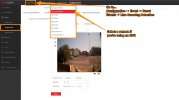
How to Configure Light Settings on Hikvision Cameras, Hikvision’s Smart Hybrid Light cameras offer a versatile solution for those who are unsure whether a black and white IR picture or ColorVu mode is best suited for a particular scene. These cameras feature both IR and white LEDs that can be used independently, allowing you to customise your lighting setup to suit your needs. Additionally, the cameras can automatically switch from IR mode to colour mode when a person or vehicle triggers an event you have set up.
This guide explains the setup for each option so that you can determine which one is best suited for your needs and scene.
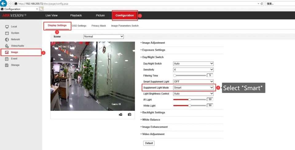
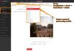
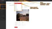
How to find the camera’s light settings in its web interface:
Even if the camera is connected to an NVR, before anything, you will need to log into the camera directly to access the advanced image and light settings to enable the different light modes, as these are not accessible from an NVR.
By default, your camera will be set to remain in ‘ColourVu only’ mode during low-light, meaning the white light will be constantly on when it is dark and never use its IR. The below sections will show you on how to configure the new ‘Smart Hybrid’ mode, ‘IR only’ mode, and ‘ColorVu only’ mode.
How do I set my camera to Smart Hybrid mode:
This mode is utilises both the IR and white LEDs built into your camera. It is useful as it allows you to keep your cameras to stay discreet in IR mode while there is no activity in your scene, and then switch to full colour when a person or vehicle is detected by putting white light on the scene, providing you with all of the additional information a colour image offers while also acting as a deterrent.
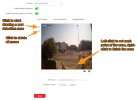
Here are the steps to enable this mode:
How do I set my camera to ‘IR only’ mode:
This mode is recommended if you would like the camera to be as discreet as possible and your scene is dark at night, as the camera will use its IR LEDs all the time at night and then switch back to colour during the day, meaning the white light is never used.
How to Configure Light Settings on Hikvision Cameras
How do I set my camera to ‘ColorVu only’ mode:
This is the opposite to IR mode, as the camera will turn on its white light at night and keep it constantly on, meaning that its IR is never used. This mode is ideal if you are not worried about the camera being discreet and prefer a colour picture 24/7.
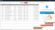
How do I find my Hikvision device and edit its network settings?
You probably want to be able to view your camera feeds remotely wherever you are; either in a web browser, the iVMS-4200 software, or the Hik-Connect mobile app. All IP CCTV devices communicate over your LAN (local network) and have a unique location on the network. So, you will need to be able to locate where the device you want to view is and make sure it has the right settings for it to work on your LAN. You will then be able to access the device from a PC or mobile device, and connect it with the rest of your CCTV system.
Please follow the steps beneath to find and correctly set your Hikvision device’s network settings.
Step 1:
The first step is to work out if you need Hikvision’s SADP tool or not. If you only need to discover and access an NVR and some Plug and Play cameras connected directly to its PoE ports, then you don’t need to use it.
If you aren’t using the SADP tool:
Or, on the NVR’s local GUI (Graphical User Interface – when operating the recorder from a connected monitor and mouse), go to:
System → Network → TCP/IP
Here, you can view and change the NVR’s network settings to match your LAN which is explained in step 2 – you can then ignore the rest of the steps.
If you are using SADP:
If your cameras are connected to your LAN, rather than to an NVR’s PoE ports, you will need to install the SADP tool. This scans for all Hikvision devices on your LAN by their MAC addresses. Now, follow steps 2-5 below.
Step 2:
You now need to identify some of your LAN’s settings, which you need to set to match on your devices.
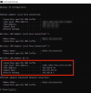
From a Window’s PC, you will need to use the Command Prompt tool to find these.
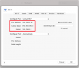
If you’re using a Mac, then you can find these by launching System Preferences, and then going to:
Network → Advanced (make sure your Wi-Fi/Ethernet connection is selected on the LHS) → TCP/IP
Make a note of the following numbers, as you will need to use them when changing your device’s network settings:
IPv4 Address – This is the IP address of the computer that you are using. This address is therefore already occupied, so you will not be able to assign any other devices to this specific address. The digits after the final decimal point indicate where the device is located within the range of your local network, which spans 1-254. You’ll need to change the number after the third period (or full stop/dot) to something that is between “1” and “254” and not already occupied by another device on the LAN.
NB – Please see these guides for instructions on checking if a proposed IP address is occupied:
How-to: How do I find my router and PC’s IP address using a Windows PC?
How-to: How do I find my router and Mac’s IP address using a Mac?
Subnet Mask – This shouldn’t need to be changed on the NVR, it will usually be “255.255.255.0”.
Default Gateway – This is the IP address that’s been assigned to your router. Any device being added to your system needs to be within the range of your gateway in order to be discoverable.
Step 3:
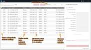
Now, launch the SADP tool again. It should show a list of all the Hikvision devices on your local network and their default network settings. Provided the device is being powered and has a connection to your LAN, then it will show up here. You can also alter the device’s network settings here, and check things like the model number, serial number, the firmware version installed on it.
NB – Remember that any camera that is directly connected to your NVR’s PoE ports will not show up in SADP. This is because the NVR hides any cameras directly connected to it from SADP on its own “subnet”, which is separate from your local network. Don’t worry though, as you won’t need to change the settings for these cameras.
Step 4:
Tick the box beside your device to view and edit the network settings.
If the device hasn’t yet been connected to the network then it will show as “Inactive”. You will be asked to set a password for it when you click the tick-box for it. For more instructions on activating your device, please see Part 6.
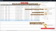
Once activated, ticking the box beside your device will change the network settings in the “Modify Network Parameters” window, so that they match your LAN. You need to make sure that you enter the password for that device before clicking “Modify” for these changes to be saved.
Step 5:
Check that these changes have been reflected in the SADP device table – you may need to wait a few minutes before refreshing. If they have, then you should be to carry on with getting this device connected to the rest of your system.
NB – If you aren’t the camera’s first owner then you will need to perform a hard reset on it. This will reset the device to its inactive factory state so that you can set new password by activating the camera in SADP. Once this has been done, SADP will allow you to modify each network setting edit the network settings to match your LAN so that you can use the device standalone or add it to your NVR remotely.
How do I set up events and email or push notifications on my Hikvision camera?
Video Analytics, or “VCA events”, are some of the most useful features available on a Hikvision camera. Using these will mean that your footage is analysed in real-time for any activity or abnormalities with your system that you would like to receive an alert for. The different events that are available currently (which ones are available varies which each model of camera) include:
This guide will cover the setup of three of the most popular event options:
Motion Detection – This is one of the first AI options that was introduced and will analyse your footage for any moving object in a specified part of your scene and can alert you as soon as it is detected. As it detects motion in its most basic sense, it uses less of a camera or NVR’s processing power than the other event options, meaning it is always available regardless of your video compression settings.
If you are not using a device with AcuSense then this option will give you the most false-positive alerts, as it offers the fewest ways for filtering out moving objects that you are not interested in, such as object size and the direction or duration of the motion.
Intrusion Detection – This is similar to motion detection in that it will alert you when a moving object is detected within a predefined “intrusion zone”. However, this is better if you want more control over when you are alerted as it will only notify you when a moving object enters the zone, rather than whenever movement occurs within it. This event type also allows you to specify the size of trigger objects, as well as how much of an object enters the zone and for how long before you are alerted.
Line Crossing Detection – This option is particularly useful for various entrances, boundaries, and roads, etc., as it allows you to draw a line in your scene so that you are notified when an object moves across that line. Importantly, you can specify the direction(s) of movement across the line on which you are notified. Like intrusion detection, you also have more control over the size of the trigger object and how much of it must cross the line.
Note – Before starting, you will need to check that your Default Gateway and DNS Server are correctly set up in your device’s network parameters, as these need to be right in order for you to be sent email notifications. To check these, please see part 2.
Section 1: Setting up motion detection
Step 1:
Connect to your device’s web browser interface by browsing for its IP address and log into it. If it is recording to an NVR, then connect to this, as this is where you should set your events from.
Step 2:
Once you’re in, navigate to:
Configuration → Event → Basic Event → Motion
If you’re using an NVR, select your camera from the “Camera” dropdown.
Note – To set one of the other VCA event options, you’ll need to go to “Smart Event” rather than “Basic Event”, where you will be shown a list of tabs with all the other available events on your camera.
Step 3:
Tick the “Enable Motion Detection” box.
Step 4:
Decide if you want to enable “Dynamic Analysis for Motion”. When this is turned on, green squares will show on anything that triggers motion detection in the camera’s feed, which can help with identifying exactly what has triggered the event.
Note – Cameras usually determine what is ‘motion’ in your scene by detecting pixel changes in the image, as a large amount of pixel change usually indicates movement. However, if there is lots of visible noise in your image due to gain control in low light, you will probably see a high number of false alerts on the camera. Using one of the more advanced event types, or the camera’s built-in LEDs to illuminate the scene, will help here.
Step 5:
Once you’re happy with the view of your scene, click on the hexagon or “Draw Area” button in “Area Settings”, which will allow you to use your mouse to draw the area within which you would like motion detection to be active.
On Easy IP 3.0 and earlier cameras, These areas will be indicated by a red grid or polygon that appears when you click on part of the scene.
The newer cameras will get you to draw one solid shape for each of your detection areas by left-clicking to set each point of that shape. When you have set all the points that you need, right-clicking will complete the shape and allow you to draw any others that you need.
To clear your zones, just click the cross or “Clear All” button.
Note – If you are not using an AcuSense camera or NVR, then you should make sure that the edges of your detection zones are not on top of anywhere that is likely to see a lot of movement, shadows, or reflections (e.g. roads, foliage, windows or the sky), to mitigate the number of false triggers.
Step 6:
If you’re using an EasyIP 4.0 camera, draw any more detection zones that you need by repeating step 5 above.
Step 7:
Adjust the “Sensitivity” bar if you need, which determines how sensitive the detection is to pixel changes. The higher the sensitivity, the more easily motion detection is triggered, meaning you will receive more alerts as a result.
A good starting point for the sensitivity is 60, but you will likely need to tweak this yourself over time to identify the optimum setting for your scene.
If there is lots of activity in your scene, then avoid setting the sensitivity too high so that you don’t receive lots of false-positive triggers.
Note – In the case of Line Crossing and Intrusion Detection, the sensitivity setting refers to the amount of an object that is needed to cross the line, or enter the box that you’ve drawn, before the event is triggered.
Step 8:
If you’re using AcuSense features, then use the “Detection Target” boxes to specify what you want to trigger the event. You can select both “Human” and “Vehicle” here if you are interested in both.
Step 9:
Click “Save” at this point so that you don’t lose these settings.
You’ll now need to go to the “Arming Schedule” and “Linkage Method” pages to set when you would like the event to be active, and what you would like to happen on triggers.
Please refer to sections 4 and 5 below for instructions on how to set these things.
Section 2: Setting up line crossing detection
Step 1:
In a web browser, go to:
Configuration → Event → Smart Event → Line Crossing Detection
If you’re using an NVR, select your camera from the dropdown at the top of the page.
Step 2:
Tick the “Enable Line Crossing Detection” box.
Step 3:
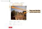
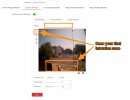
Click on the line button or “Draw Area” to draw your line on the video feed – you can move, rotate or resize however you like.
Step 4:
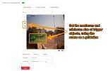
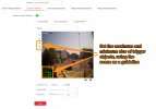
Set your maximum and minimum target sizes by clicking the size filter buttons, and drawing these on the camera preview.
Anything that crosses your line and is smaller than your minimum box, or larger than the maximum box, at the point of the line, will not trigger the event.
You should use objects or vehicles in the scene to guide you here. For example, I have set the minimum target size to be slightly smaller than any car that’s near where I’ll draw my line, and the maximum to be slightly larger than a large HGV.
Note – It doesn’t matter where boxes are on the feed. Also, these boxes will only be visible on this event page, and will not show up on your footage in the live view or playback pages.
Step 5:
If you’re using an AcuSense camera or NVR, then specify the “target(s)” that you would like to trigger the event by ticking the box. There is no issue with ticking both “Human” and “Vehicle” here.
Step 6:
Specify your “Direction”, which refers to the direction from which an object much cross your line to trigger the event. The different options available are explained beneath:
A<->B – Any object crossing from either direction will trigger
A->B – Any object crossing from side “A” to side “B” will trigger (In this case, from left to right)
A<-B – Any object crossing from “B” to “A” will trigger (In this case, from right to left)
Step 7:
Adjust the sensitivity bar to suit your needs. Setting this high will reduce the amount of an object that is needed to cross your line before this is triggered. This will, of course, result in more triggers. As the optimum setting here depends on how busy your scene is, we recommend starting at 60 and then adjusting the bar over time until you find the best results.
Step 8:
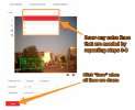
Use the “Line” dropdown to select and draw any more lines, repeating steps 2-8 above.
Step 9:
Click “Save” at this point so that you don’t lose these settings.
You’ll now need to go to the “Arming Schedule” and “Linkage Method” pages to set when you would like the event to be active, and what you would like to happen on triggers.
Please refer to sections 4 and 5 below for instructions on how to set these things.
Section 3: Setting up intrusion detection
Step 1:
In a web browser, go to:
Configuration → Event → Smart Event → Intrusion Detection
If connected to an NVR, select your camera from the dropdown at the top of the page.
Step 2:
Tick the “Enable Intrusion Detection” box.
Step 3:
Click on “Draw Area” to draw your intrusion zone (or “Detection Area”) on the video feed, which can be a 3 or 4 sided shape. Left-click on the camera preview to set each of these points. Once your zone is drawn, you can still move each of the points to change the shape to better fit your area of interest.
Note – If the edges of your zone are very close to a road, foliage, or anywhere that is likely to see lots of movement, then you will likely see a number of false-positive alerts. This is because any movement on these lines can trigger the event. If you can, you should allow for a bit of a gap between these parts of the scene and your intrusion zone.
Step 4:
Set your maximum and minimum target sizes by clicking the “Size Filter” buttons, and drawing these on the live camera feed above.
Anything that enters your configured intrusion detection zone and is smaller than your “Min” box, or larger than the “Max” box, will not trigger the event.
You should use objects or vehicles in the scene to guide you here. For example, I have set the minimum target size to be smaller than the smallest person I’d expect to see in that part of the scene, and the maximum to comfortably cover a very tall person.
Note – It doesn’t matter where boxes are on the feed. Also, these boxes will only be visible on this event page, and will not show up on your footage in the live view or playback pages.
Step 5:
If you’re using an AcuSense camera or NVR, then specify the “target(s)” that you would like to trigger the event by ticking the relevant box. There is no issue with ticking both “Human” and “Vehicle” here.
Step 6:
Now, adjust the “Threshold” bar as you need. This can be set between 1 and 10 seconds and refers to how long an object needs to be within your intrusion zone before triggering the event. For example, setting this to “0” will mean that the event is triggered as soon as a valid target enters your zone.
Step 7:
Adjust the sensitivity bar to suit your needs. Setting this high will reduce the amount of an object that is needed to enter your zone before the event is triggered. This will, of course, result in more triggers. As the optimum setting here depends on how busy your scene is, we recommend setting this to 60 and then adjusting the bar over time until you find the best results.
Step 8:
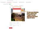
Use the “Region” dropdown to select and draw any more intrusion zones, repeating steps 2-6 above.
Step 9:
Click on the “Arming Schedule” tab and set this by filling in the hours you want the event to be enabled for in blue.
Note – Please see section [1] step 9 above for a more detailed explanation on how to set your arming schedule.
Step 10:
Click “Save” at this point so that you don’t lose these settings.
You’ll now need to go to the “Arming Schedule” and “Linkage Method” pages to set when you would like the event to be active, and what you would like to happen on triggers.
Please refer to sections 4 and 5 below for instructions on how to set these things.
Section 4: Setting the Arming Schedule for your events
Now that you have set your “Area Settings”, click on the “Arming Schedule” tab to set when the event will be active.
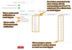
This will bring up a timeline with the week broken up into days and hours – depending on the device that you are using, it might look different to the grid below. If a period is filled in blue then the event will be active (or “armed”) for that hour; If the period is white, the event will be off.
Use your mouse to draw up the weekly Arming Schedule that suits. You can also use the popup box that appears when you click on any blue period to finely adjust the start arming times:
Clicking on the “Erase” button and then a blue period will allow you to clear the arming:
When you’re happy with this schedule, click “Save”.
Section 5: Setting up email & push notifications for your events
Click on the Linkage Method tab on the event’s page (shown above), which is where you will set up your email notifications, as well as other alert types.
The different options are explained below:
Audible Warning: This will cause the NVR / browser to bleep when on event triggers.
Send Email: This will set the NVR to email you on event triggers, with a screenshot of the camera’s view at the time.
Notify Surveillance Centre: This refers to Hik-Connect and needs to be activated in order to receive push notifications in Hik-Connect.
Full Screen Monitoring: This will get the NVR to automatically throw up a camera’s live feed in full screen during a trigger for an event set on that camera.
To enable Hik-Connect push notifications:
To set up push notifications, you need to make sure that Notify Surveillance Centre is ticked as a “Linkage Method”.
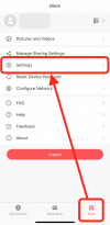
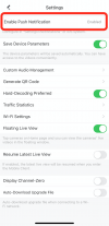
You also need to make sure that push notifications are enabled for Hik-Connect in your phone’s settings. To enable them via the app, go to:
More → Settings → Enable Push Notification
……..
